SpineDepth
SpineDepth is a dataset of labelled RGB-D videos of pedicle screw placement performed on ten human cadaveric lumbar spines. Along with each video, individual ground truth 3D pose and shape data for spine levels L1-L5 are provided.
Procedure and recordings
In each specimen, 10 pedicle screws were inserted bilaterally on levels L1-L5 in different orders (see table below). The procedure was recorded with 2 RGB-D sensors (Stereolabs ZED Mini) from viewpoints resembling the ones of a surgical headlight or an OR light. For each screw, these viewpoints were altered and the sensors were extrinsically calibrated to an optical tracking system for ground truth 3D pose data capturing. Subsequently, separate recordings of the following 4 surgical steps were acquired:
Determining the correct entry point using anatomical landmarks and open bone cortex with a luer
Development of the screw canal with a surgical awl to a fully intraosseous trajectory
Verification of the integrity of bony canal with a K-wire
Placement of a measured screw implant in the previously established canal
This resulted in 40 recordings (10 screws x 4 surgical steps) from 2 different viewpoints each (80 videos) per specimen.
Provided data
Due to very large file sizes, the data was split into 10 packages, one for each specimen.
The videos are provided in Stereolabs SVO file format and can be processed as needed using the ZED SDK: Link
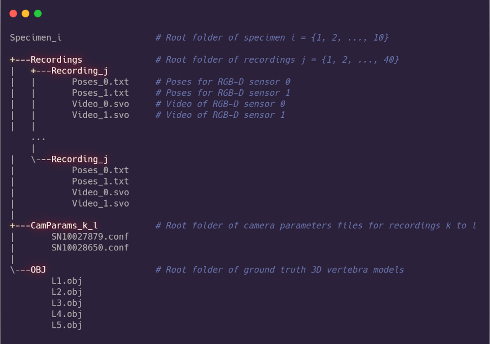
The videos need to be opened with the correct file of camera parameters for each sensor placed in the settings directory (Calibration File). These files are provided for each specimen. Their filenames should not be changed as they represent the serial numbers of the sensors. Please note that for some specimen, the sensors were recalibrated during data acquisition. Therefore, the folder name containing the camera parameter files indicates the index of the first and last recording for which those files are valid. If there are multiple folders, the files in the Stereolabs settings directory need to be swapped accordingly. E.g. a folder "CamParams_0_7" contains the camera parameter files to be used for the 8 recordings 0 to 7.
For each video, the respective ground truth poses are provided in .txt files. The sensors had different viewpoints for the same recording. Consequently, ground truth poses are provided for each sensor separately ("Poses_0.txt" and "Poses_1.txt"). Thereby, the first 5 rows in the file belong to the first frame of the respective video. Each row represents the pose of 1 vertebra (row 1 for L1, row 2 for L2, etc.), written as a 3 x 4 transformation matrix, to be read in row-major order. Rows 6-10 then belong to the second frame of the respective video recording, and so on.
Ground truth 3D vertebra models of levels L1-L5 are provided in OBJ format. For each frame of each video, they can be transformed by the respective poses mentioned above.
Data structure
Each package is structured as depicted below.
Data Access
| Specimen | Type* | Screw Order** | # of frames | Download |
|---|---|---|---|---|
| 1 | Midline Approach | L1-L5 | 22553 | Download (Zip, 118 GB) |
| 2 | Full Exposure | L1-L3, L4-L5 | 34302 | Download (Zip, 176 GB) |
| 3 | Full Exposure | L1-L2, L3-L5 (LLL, RRR) | 33489 | Download (Zip, 166 GB) |
| 4 | Full Exposure | L1-L5 | 37497 | Download (Zip, 183 GB) |
| 5 | Vollständige Freilegung | L1-L3, L4-L5 | 31279 | Download (Zip, 158 GB) |
| 6 | Vollständige Freilegung | L3-L4, L4-L5, L1-L2 | 30249 | Download (Zip, 152 GB) |
| 7 | Vollständige Freilegung | L4-L5, L1-L3 | 25746 | Download (Zip, 127 GB) |
| 8 | Full Exposure | L2-L4, L4-L5, L1-L2 | 27679 | Download (Zip, 134 GB) |
| 9 | Full Exposure | L1-L5 | 24403 | Download (Zip, 120 GB) |
| 10 | Full Exposure | L4-L5, L1-L3 | 32359 | Download (Zip, 156 GB) |
* Midline approach: Soft tissue structures were intact and a standard midline approach for instrumentation of pedicle screws from level TH12-S1 had been performed. Full exposure: Specimen freed from soft tissues such as the paravertebral muscles to expose the dorsal bony anatomy (care had been taken not to damage the intraspinous ligament, the ligamentum flavum as well as the facet joint capsule).
** For each comma separated group, screws were inserted in ascending order of levels. Previously inserted screws were removed before moving on to the next group. If previously inserted screws are present in a subsequent group, these screws were not removed. If not indicated otherwise, screws were inserted bilaterally (left, then right) before moving on to the next level.